

Next: About this document ...
Up: SAA (SSPLab AudioAnalyser)
Previous: Download
Buttons under Edit is not functional yet
1)Opening an existing file.
File->Open
2)To play
Signals -> Play
3)To record a stream.
a) Choose the bits (click on the checkbox)
b) Choose the sampling rate (click on the checkbox)
c) Choose the number of channels. (click on the checkbox)
d) Plug in the sound source like mirophones to the sound card.
e) Check your mixer settings (not yet controllable from saa)
f) Choose new file
File -> New
g) Set the time for recording by typing it in the box
(Not yet controlable in between the recording)
h) Start recording
Signals -> Record
4)To normalize the amplitude to 1
Process->Normalize
5)To separate the sources recorded from a stereo recording with
microphones placed 13cm apart. Use cardioid microphones.
Use a preamplifier so that you can make use of the 'line in' of
your sound card for stereo recordings. (Such a kit can be sold
as a product along with this software :)). It works reasonably
well in a less reverberant room.
a)Record a peice with more that one source or open a previously
recorded file. (At present the algorithm works only are 44.1kHz.)
b)Start separation by
Process->Sep. final
c)When the processing is over a window pops up from which you
can choose and play the desired sources.
d)You can save these sources if you want using the buttons on this
new window.
The program uses basic C coding of classically available literature
and some of the techniques we have developed in our lab (SSPLab,
IISc, India). The main component of the latter class of techniques
is the auditory scene analyzer. This tries to replicate some of the
functionality of human auditory system. This feature makes SAA unique
among the available software for sound processing. (The details are
under review as paper and would be online soon :))
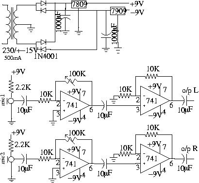
To make use of this auditory scene analysis feature you need to have
a stereo preamplifier facility or construct a small circuit as described
below, to be used along with your sound card line in. This circuit
is a stereo preamplifier to condition the microphone output so that
the signal levels are compatible with requirement for line-in of the
sound card. The circuit diagram is given in figure (![[*]](file:/usr/share/latex2html/icons/crossref.png) )
)

|
Figure:
On the left is the circuit diagram for the preamplifier
and microphone setup to be used with the sound-card line-in. The microphones
are electret microphones. All resistors are 1/4 watts. The capacitors
are rated 25V. We used Labtec Verse303 microphones. It is up to you to
design or buy a better stereo preamplifier circuit
|

|
Figure:On the left is the finished circuit inside the box.
(![[*]](file:/usr/share/latex2html/icons/crossref.png) ). The output from this
preamplifier and microphone setup goes to the sound-card line-in. ). The output from this
preamplifier and microphone setup goes to the sound-card line-in.
|

|
Figure:On the left is the finished setup connected to the computer. Mic 2 is not
vissible because it is on the other side of the box.
|

|
Figure: Schematic top view of the recording setup while recording is done.
|

|
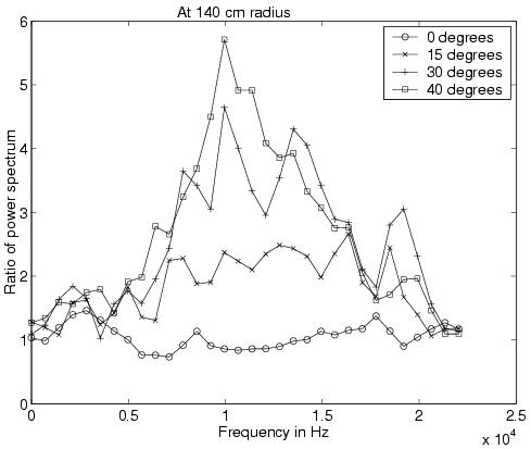
Figure:Box Related Transfer Function (BRTF) for the above box represented as ratio of
magnitude spectrum of white signal received at the two sides of the box at various Directions of
Arrival (DOA) from the broadside.
|


Next: About this document ...
Up: Download
Previous: Download
Joby Joseph
2003-10-10
![]() )
)